- 您现在的位置:买卖IC网 > Sheet目录101 > NHD-24064WG-ATGH-VZ# (Newhaven Display Intl)LCD MOD GRAPH 240X64 WH TRANSFL
[4]?�
� ?�
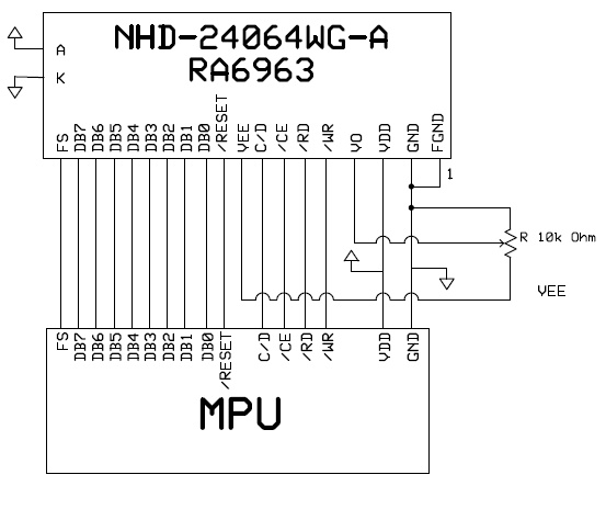
� Pin?Description?and?Wiring?Diagram?�
� Pin?No.?�
� Symbol?�
� External?�
� Connection?�
� Function?Description�
� 1?�
� FGND?�
� Power?Supply?�
� Frame?Ground�
� 2?�
� VSS?�
� Power?Supply?�
� Ground�
� 3?�
� VDD??Power?Supply?�
� Power?supply?for?logic?(+5.0V)?�
� 4?�
� V0?�
� Adj.?Power?Supply?�
� Power?supply?for?contrast?(approx.?‐7V)�
� 5?�
� /WR?�
� MPU?�
� Active?LOW?Write?signal�
� 6?�
� /RD?�
� MPU?�
� Active?LOW?Read?signal�
� 7?�
� /CE?�
� MPU?�
� Active?LOW?chip?enable�
� 8?�
� C/D?�
� MPU?�
� Register?select?signal??C/D=0:?DATA??C/D=1:?COMMAND?�
� 9?�
� VEE?�
� Power?Supply?�
� Negative?voltage?output?(‐10V)�
� 10?�
� RESET?�
� MPU?�
� Active?LOW?reset?signal�
� 11~18?�
� DBO~DB7?�
� MPU?�
� 8‐bit?Bi‐directional?data?bus?�
� 19?�
� FS?�
� MPU?�
� Font?Select:�
� 1=6x8?fonts,?0=8x8?fonts�
� 20?�
� NC?‐No?Connect�
� A?�
� LED+?�
� Power?Supply?�
� Power?supply?for?LED?Backlight?(+3.5V)�
� K?�
� LED‐?�
� Power?Supply?�
� Ground?for?Backlight�
� ?�
� Recommended?LCD?connector:?2.54mm?pitch?pins?�
� Backlight?connector:?JST‐XHP‐3????Mates?with:??B?3B‐XH‐A?�
� ?�
� ?�
�  �
�
� � �  �
�
� � 发布紧急采购,3分钟左右您将得到回复。
相关PDF资料
NHD-24064WG-ATMI-VZ#
LCD GRAPH 240X64 WT TRANSM
NHD-24064WG-AYYH-VZ#
LCD MOD GRAPH 240X64 Y/G TRANSFL
NHD-3.12-25664UCB2
LCD OLED GRAPHIC 256 X 64 BLUE
NHD-3.12-25664UCY2
LCD OLED GRAPHIC 256 X 64 YLW
NHD-3.5-320240MF-ATXL#-1
LCD DISP TFT 3.5" 320X240 B/L
NHD-3.5-320240MF-ATXL#-CTP-1
DISPLAY TFT MODULE W/TOUCH
NHD-3.5-320240MF-ATXL#-T-1
LCD DISP TFT 3.5" 320X240 B/L
NHD-3.5-320240YF-ATXL#-T
LCD DISPL TFT 3.5" 320x240 WH+TP
相关代理商/技术参数
NHD-24064WG-ATMI-VZ#
功能描述:LCD 图形显示模块和配件 240 x 64 STN-BL (-) 180.0 x 65.0 RoHS:否 制造商:ELECTRONIC ASSEMBLY 产品: 分辨率:128 x 64 流体类型:FSTN Positive 接口: 背光: 背景色:White 工作温度范围:- 20 C to + 70 C 封装:Bulk
NHD-24064WG-AYYH-VZ
制造商:NEWHAVEN 制造商全称:NEWHAVEN 功能描述:Graphic Liquid Crystal Display Module
NHD-24064WG-AYYH-VZ#
功能描述:LCD 图形显示模块和配件 STN-Y/G Transfl 180.0 x 65.0 RoHS:否 制造商:ELECTRONIC ASSEMBLY 产品: 分辨率:128 x 64 流体类型:FSTN Positive 接口: 背光: 背景色:White 工作温度范围:- 20 C to + 70 C 封装:Bulk
NHD-24-240320SF-CTXI
制造商:NEWHAVEN 制造商全称:NEWHAVEN 功能描述:TFT (Thin-Film Transistor) Liquid Crystal Display Module
NHD-3.12-25664UCB2
功能描述:OLED显示器和配件 OLED 256 x 64 Blue 89.2 x 44.0 x 6.0
RoHS:否 制造商:4D Systems 工作电压:4 V to 5.5 V 工作电流:40 mA 最大工作温度:+ 70 C 最小工作温度:- 30 C 封装:Bulk
NHD-3.12-25664UCY2
功能描述:OLED显示器和配件 OLED 256 x 64 Yellow 89.2 x 44.0 x 6.0
RoHS:否 制造商:4D Systems 工作电压:4 V to 5.5 V 工作电流:40 mA 最大工作温度:+ 70 C 最小工作温度:- 30 C 封装:Bulk
NHD-3.12-25664UMB3
功能描述:OLED显示器和配件 OLED 256x64 Blue 3.12" Multi-Font 3V
RoHS:否 制造商:4D Systems 工作电压:4 V to 5.5 V 工作电流:40 mA 最大工作温度:+ 70 C 最小工作温度:- 30 C 封装:Bulk
NHD-3.12-25664UMY3
功能描述:OLED显示器和配件 OLED 256x64 Yellow 3.12" Multi-Font 3V
RoHS:否 制造商:4D Systems 工作电压:4 V to 5.5 V 工作电流:40 mA 最大工作温度:+ 70 C 最小工作温度:- 30 C 封装:Bulk